1. Introduction
In Part One of this series, we studied refraction through a slab where the surfaces separating the two media, like air and glass, were parallel. We saw that the emergent ray leaves the slab parallel to the incident ray. In this blog, we will study the case of a prism with inclined surfaces at the entry and exit points of the medium. A prism is a solid object with two types of faces: base and lateral. The lateral faces are rectangular or square; the base can be a triangle, square, or pentagon. In Part 1 of this blog series, we already discussed right-angled prisms that deflect the ray by 90 ⁰ using the phenomenon of total internal reflection. In that case, light entered and exited normally from the prism’s surface. Hence, the ray was not refracted. Further, in this blog, we will see that because the refractive index of a medium is wavelength-dependent, the constituent colors will deviate in different directions, leading to the dispersion of light. In the following three sections, we will investigate the structure of the prism and the ray tracing of monochromatic and white lights.
2. Refraction by a prism
The prism most commonly used in optics has two base faces XYZ and X’Y’Z’ that are equilateral triangles and three lateral faces as shown in Figure 1A. The lateral face Z’Y’YZ is perpendicular to the line of sight.
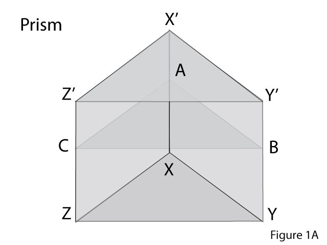

Figure 1B shows section ABC of the prism in Figure 1A parallel to the base. The incident ray SO from source S strikes the surface CA at point O. The line NOM represents normal to the surface at O. The incident ray bends towards the normal on refraction along OP. The angle of incidence is i = ∠NOS. The angle of refraction is r = ∠ MOP. The ray undergoes refraction again at point P at the surface AB. Let us draw normal RPF to this surface at point P. The refracted ray PT bends away from the normal as it emerges from the glass into the air. The angle of emergence i’ = ∠TPR. We saw in Blog 1 of this series that the incident and emergent rays were parallel in the case of refraction across a slab. That was because the two surfaces where refractions occurred were parallel. In the prism, these two faces are inclined at an angle A. The deviation of the incident ray at the first surface at point O is δ1 =∠POD. The deviation at the exit surface at P is δ2= ∠ DPO. Let the extended incident ray SOU meet the extended emergent ray TP at point D. The total deviation suffered by the incident ray emerging from the prism is ∠TDU = δ. The angle δ is called the angle of deviation.
In triangle ODP, the exterior angle δ is given by : δ = δ1 + δ2 δ = ( i – r ) + ( i’ – r’ ) Eq. 1
In triangle OPM, the exterior angle
∠ OMF= r + r‘ Eq. 2
In the quadrilateral OAPM,
∠AOM = ∠APM = 90⁰.
Therefore the sum of the remaining two angles
∠A + ∠PMO = 180⁰ Eq. 3
A = 180⁰ – ∠PMO
= ∠ OMF
from Eq. 2, A = r + r’ Eq. 4
From Eqs. 1 and 4
δ = ( i + i’ ) – A Eq. 5
3. Angle of minimum deviation
For a given prism of refracting angle A and refractive index μ, let us calculate the variation of δ with the angle of incidence i. For this, we rewrite Eq. 5 to express i’ in terms of i :
Applying Snell’s law of refraction at point P,
sin i’ = sin r‘ * μ
i’ = sin –1 ( sin r‘ * μ)
From Eq. 4, r’ = A – r, hence
i’ = sin –1 ( sin (A – r) * μ) Eq. 6
Applying Snell’s law of refraction at point O,
sin r = sin i / μ
r = sin -1 ( sin i / μ )
Substituting value of r in Eq. 6,
i’ = sin –1 ( sin ( A – sin -1 ( sin i / μ )) * μ)
Substituting for i’ in Eq. 5 ,
δ = ( i + sin –1 ( sin ( A – sin -1 ( sin i / μ )) * μ)) – A Eq. 7
Equation 7 gives variation of δ in terms of known values of i, μ and A.
(The student can independently attempt getting this relation between δ and i , for a good grasp of the refraction process through a prism)

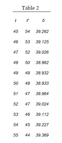
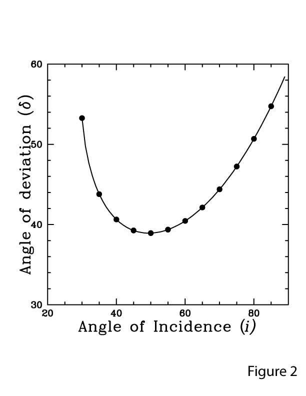
Table 1 gives the values of i’ and δ calculated using Eqs. 7 for values of i from 30⁰ to 85⁰ at 5⁰ intervals. Table 2 gives the variation in these angles from 45⁰ to 55⁰ at 1⁰ intervals. The refractive index of the material of the prism is taken as 1.52. Figure 2 shows the variation of the deviation angle δ with the incidence angle i. As the value of i increases, δ decreases at first, reaches a minimum value at i ≅ 50⁰, and increases afterward. The minimum value of δ is called the angle of minimum deviation δm. (The student can repeat the calculations for a different refractive index value and compare it with the curve in Figure 2). From Table 2, it is seen that at minimum deviation i = i’. Using differential calculus, we can prove that δ is minimum when i = i’. However, this is beyond the scope of this blog.
It follows from Snell’s law that when i = i’, r = r’, the △OPM becomes an equilateral triangle. Hence, when the angle of minimum deviation is minimum, OP is parallel to BC, that is , the refracted ray through the prism is parallel to the base.
From Eqs. 4 and 5, at δ = δm
r =A/2
δm= (2 i ) -A
i = ( A + δm )/2
μ = sin i / sin r = sin ((A + δm )/2) / sin (A/2) Eq. 8
The refractive index of the medium of the prism can be determined by measuring δm and A as shown in the next section.
4. The Prism spectrometer
A prism spectrometer is an instrument to measure the angles of incidence and deviation through a prism. Figure 3A shows th schematic diagram of a prism spectrograph used for this experiment. A monochromatic source of light S, such as a Sodium vapor lamp, is placed in front of the collimator. The radiation from the sodium vapor lamp is a doublet with wavelengths of 569.0 and 569.56 nanometers. These are close enough to be considered monochromatic for most purposes.

The position of the narrow slit S in front of the source can be adjusted to be at the focus of the collimator lens Lc. Light emerging out of the collimator will then be a parallel beam. Here, in the schematic diagram, we show only the axial ray to trace the path through the prism. The prism is mounted on a turn table with the base face XYZ resting on the table. The light ray strikes the lateral face ZZ’X’X at point O, gets refracted, and meets the opposite lateral face YY’X’X at point P. On refraction from this surface, the ray emerges along PQ. The telescope focuses the image of the slit on its focal plane. The image can be viewed through an eyepiece with a cross wire. The eyepiece assembly can be moved along the axis. The collimator, the prism table, and the telescope can be rotated along a fixed vertical axis passing through the center of the prism table. The positions of the telescope and collimator are read on the circular dial with a vernier scale ( not shown in the figure). Both the base faces and one of the lateral faces, ZZ’Y’Y, are grounded to get a rough frosted finish to reduce stray light entering the prism. The main instrument and the prism table are carefully leveled to ensure the prism’s base is perpendicular to the rotation axis EE’.
The refractive index of the medium of the prism can be determined by measuring δm and A. The method is described in the following two sub-sections.
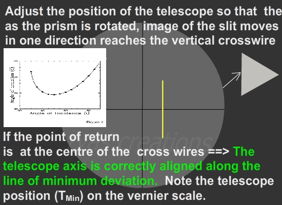
4.1 Experimental procedure to determine the angle of minimum deviation δm.
The procedure to determine the angle of minimum deviation is explained in the following video:
4.2 Experimental procedure to determine the angle of prism A
Although the manufacturer provides the prism angle, it is a good idea to determine it experimentally using the prism spectrometer for precise measurement. The prism is mounted such that the edge XX’ faces the collimator. The prism table is adjusted so that the parallel beam of light falls on the two lateral faces, ZZ’X’X and YY’X’X symmetrically. The cross-section ABC of the prism is shown in Figure 3B.
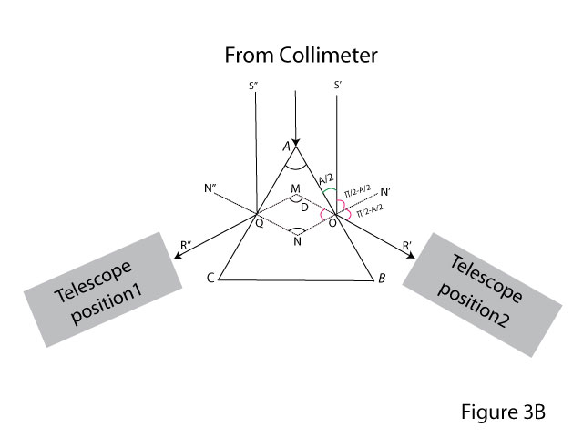
The axial light rays S’OR’ and S”QR” are shown in the figure 3B representing the right and left halves of the beam after reflection from the two faces. The telescope is turned towards the left beam and the position of the image of the slit is adjusted to coincide with the vertical crosswire. Let the vernier scale reading be TL representing direction R”QM . Similarly let TR be the telescope position representing the direction R’OM.
The angle M= TR – TL
= 2A
The above relation between M and A can be obtained using simple geometry and is left for the student as an exercise.
5. Dispersion of polychromatic light through a prism
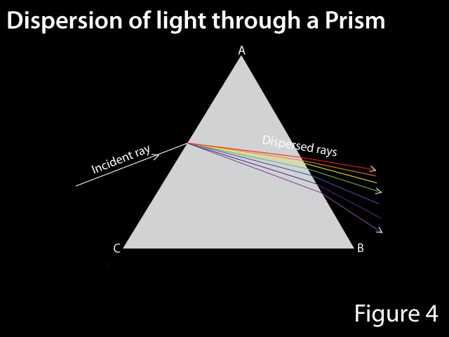
Until now, we assumed the light to be monochromatic, for example, the yellow light of a sodium vapor source. If one uses an incandescent light like a filament bulb there will be a spread of wavelength. The wavelength of emission lines radiated by lamps such as Thorium–Argon hollow cathode lamps or low-pressure mercury lamps is accurately known. These lamps are used as comparison lamps in spectrometers for calibration. As the refractive index of the medium is wavelength dependent, rays will be deviated by different extents on passage through a prism. The refractive index of a given medium increases with decreasing wavelength. Violet light at around 380 nanometers wavelength deviates more than red light at around 760 nanometers. Hence, light from a white light source is split into the component colors due to the difference in deviation as shown in Figure 4. White light is said to be dispersed.
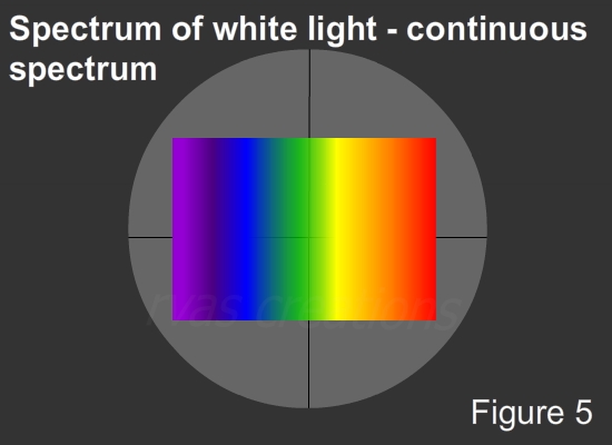
A view of the spectrum of white light from the filament lamp through the eyepiece is shown in Figure 5. This is a continuous spectrum. The Intensity profile varies according to the temperature of the source. If we gradually increase the source’s temperature by regulating the voltage, the filament first becomes red, orange, white, blue and so on. This is because the peak of the intensity distribution across the spectrum of radiation will shift towards a shorter wavelength as the filament temperature increases.
Instead of a continuous spread in wavelength, if the source has discrete lines, the view from the eyepiece will appear as shown in Figure 6. This is called a line spectrum.

6. Conclusion
We discussed the refraction of light in the Blog1 of this series and saw why a ray of light gets refracted on entering from one medium to another. Refraction across a slab was considered as a starting point. As against the parallel entry and exit surfaces in a slab, we discuss in this blog what happens if these surfaces are inclined like in the case of a prism. We derived the equation to show the dependence of the angle of deviation on the angle of incidence. Experimental determinations of the angle of minimum deviation and the angle of the prism were discussed. We introduced the concept of dispersion of white light. In the next blog, we will discuss the refraction of light from curved surfaces and study lenses.
Watch the YouTube version here.