This blog aims to spark a strong interest in physics for tenth-grade students. It will guide them through optics, beginning with refraction.
1. Introduction
Optics is a branch of physics that studies the behavior of light, including refraction – the bending of light as it moves from one medium to another. This phenomenon is used to create optical instruments such as telescopes, binoculars, and microscopes. Smooth surfaces reflect light, while concave spherical surfaces focus light rays to a single point. The fascinating field of optics explores various light behaviors, including polarization, interference, and diffraction.
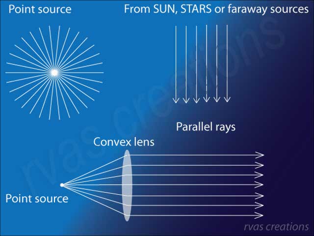
At the 10th-grade level, we focus on geometric optics, where light behavior is explained by tracing the wave direction as a ray. A light source is needed for the start. A point source at a finite distance produces a divergent beam, while light beams from distant sources like the Sun or stars are parallel. Subsequent sections will show how a convex lens can convert a diverging beam into a parallel beam, as shown in Figure 1 above.
2. Refraction of light from a rarer to a denser medium.
Imagine a light source at point S in Figure 2, emitting rays in all directions. Given the universality of the laws of physics, we can select any random ray and analyze its interaction with a block of glass or a tank of water.

As light travels in a medium, it interacts with matter. In a vacuum, there is no matter to interact with; therefore, the speed of light remains constant, denoted as c. Its speed decreases when traversing from a lighter medium like air or vacuum to a denser medium like water or glass.
The value of c is 299792458 meters per second or approximately 300,000 kilometers per second. The entire spectrum of electromagnetic waves, for example, radio waves, visible light rays, X rays, and Gamma rays, travel at the same speed in a vacuum. The optical behavior of a medium is quantified by its refractive index, defined as:
VacuumµGlass = speed of light in vacuum/speed of light in glass ( Eq. 1)
The refractive index of air is given by:
VacuumµAir = (speed of light in vacuum) / (speed of light in air) = 1.0003 ( Eq. 2)
The refractive index of a medium defined relative to a vacuum is referred to as the absolute refractive index µ. As the speed of light is largest in a vacuum, the refractive indices of other transparent materials are greater than unity.
The refractive index of glass with respect to air is given by:
AirµGlass = speed of light in air / speed of light in glass ( Eq. 3)
This can be written as:
= (speed of light in vacuum ∕ speed of light in glass) / (speed of light in vacuum ∕ speed of light in air)
= VacuumµGlass / 1.0003 ( Eq. 4)
≊ VacuumµGlass
The refractive index of glass or any other medium with respect to air is thus very close to its refractive index with respect to vacuum.
3. Geometrical Optics – Ray tracing and definition of angles
A ray from source S strikes the interface of two media at point O (see Figure 3). The normal at this point is represented by ON. The angle of incidence, denoted as angle i, is the angle between the incident ray SO and the normal ON.
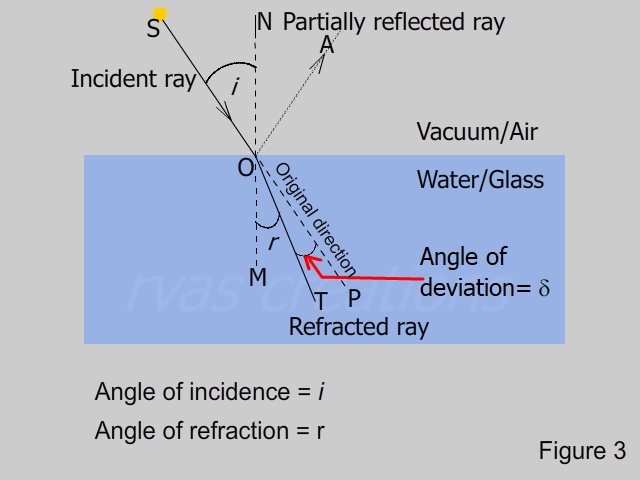
When an incident ray strikes a surface, part of it is reflected according to the laws of reflection, where the angle of reflection equals the angle of incidence. The intensity of the reflected light varies based on the surface’s smoothness and the angle of incidence, as seen in reflections in puddles or shop windows.
On entering the denser medium, the ray does not continue along the original direction but bends towards the normal. This phenomenon is called the refraction of light. A detailed explanation for this will be taught in later years when we will study the electromagnetic nature of light and its interaction with matter. The refracted ray OT makes an angle r with the normal OM to the surface. This angle is called the angle of refraction. Without the change in the medium, the ray would have traveled along OP. The ray inside the denser medium is deviated by ∠ POT from the original direction; this angle is called the angle of deviation denoted by δ.
4. Snell’s laws of refraction
Greek physicist Claudius Ptolemy measured and tabulated the angles of incidence and refraction through water in 140 AD. However, the cause of refraction was unknown at that time. Ibn Saul, an Arabian mathematician, wrote a treatise in 984 AD explaining how curved lenses and mirrors bend light and is credited with discovering the refraction phenomenon of light and the laws of refraction. Dutch mathematician Willebrod Snell independently formulated the laws of refraction in 1621 AD, which explained the measurements of the incident and refracted angles. Snell’s laws of refraction result from a careful experimental study of the behavior of the incident, reflected, and refracted rays. However, no proof was known then, and it was just a mathematical expression. The proof had to wait until the early 1860s when James Clerk Maxwell showed through his equations that fluctuations of electric and magnetic fields travel in a vacuum with a constant speed c and that light is an electromagnetic wave. Electromagnetic waves cover a broad spectrum range from long radio waves to short gamma rays, and light rays fall within a small window of this spectrum.

THE FIRST LAW: The incident, reflected, refracted rays, and the normal to surface of separation of the two media at the point of contact lie in the same plane. This is shown in Figure 4, which is a simplified version of Figure 3: the incident ray SO, the reflected ray OA, the refracted ray OT and the normal ON (extended to M in the second medium) are all in the same plane.
THE SECOND LAW: For a given pair of media, the ratio
sin i / sinr = 1μ2 (Eq.5)
is constant for light of a given wavelength.
If the first medium is a vacuum, then we drop the superscript and the subscript and write.
sin i / sin r = μ , (Eq. 6)
where μ is called the refractive index of the medium. The refractive index is constant for a given medium but depends on the wavelength of the light. Suppose the wavelength of the measured value of μ is not specified; in that case, it is taken for the yellow radiation of Sodium with an average wavelength of 589.3 nanometers ( 1 nanometer = 10 -9 ). Equation 6 represents the definition of the refractive index. The refractive indices of some of the materials are given below. A comprehensive list can be found here.
Refractive indices of some materials
Material Refractive index
Vacuum 1 (by definition)
Air at STP 1.0003
water 1.333
normal glass 1.52
Polycarbonate 1.60 (used in spectacles)
As the refractive index of air at STP is close to that of vacuum, the refractive index of any medium relative to air is approximated by the value relative to vacuum.
Snell’s laws of refraction are the result of a careful experimental study of the behavior of the incident, reflected, and refracted rays. Interestingly, two ratios, one derived from the angles (Eq. 6) and another from speeds (Eq. 1), are indeed equivalent. For a curious student, the following section provides a geometrical proof.
5. Physics of refractive index
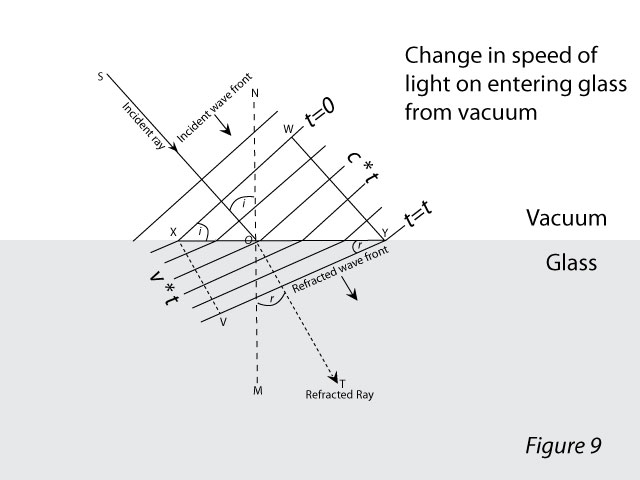
The ray of light is the direction of propagation of light energy. Light is an electromagnetic wave; the variations in the electric and magnetic vectors are perpendicular to each other and confined to a perpendicular plane to the ray. This plane is referred to as the wavefront. A two-dimensional section of a spherical wavefront from a point source is shown in Figure 7. Energy along parallel rays is carried along a plane wavefront, as shown in Figure 8. The wavefront moves with the speed of light. As mentioned in Section 2, the speed depends on the interaction of the electromagnetic field and matter..


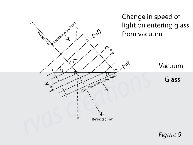
Consider a plane wavefront incident on the surface of a glass block, as shown in Figure 9. The angle of incidence is i. The line XW represents the intersection of the wavefront with the plane of the paper. Point X reaches the surface first due to inclined incidence, which we will take as t=0. As the wavefront travels, the portion of it in a vacuum travels with speed c, while the portion in the glass travels with speed v, which is less than c. Therefore, the wavefront positions at successive instances are closer in the glass than in the vacuum. When point W touches the surface of the glass at Y, point X reaches V, and the wavefront section at this instant is along VY. The incident ray is along SO (perpendicular to XY), and the refracted ray is along OT (perpendicular to VY). The angles of incidence and refraction are related to the speed of light, as shown below.
Consider the triangles XWY and XYV in Figure 9,
sin i = WY/XY ( Eq. 7)
sin r= XV/XY ( Eq. 8)
From equations 7 and 8,
sin i / sin r = WY / XV
= c * t / v * t
= c / v
= μ
Thus we see that the refractive index of a medium as defined by the modern theory as c/v (Eq. 1) and that defined by Snell’s second law as sin i / sin r (Eq. 6) are equivalent.
6. Refraction across a slab
We saw that a ray of light entering an optically denser medium bends toward the normal. In this section, we will see what happens to the ray when it leaves the denser medium and emerges back into the air at point P. Let us consider that the source is at S and the ray SO strikes a block of glass at the point O. The figure shown below is the same as Figure 3 in section 2; however, as our goal is to study refraction, we ignore the fainter partially reflected ray OA.
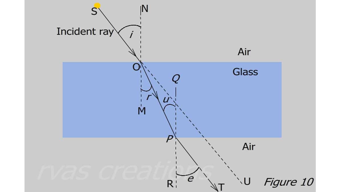
Because the ray is going from dense (glass) to a rare medium (air) , the ray bends away from the normal PR and travels along PT.
Let the angle of refraction = ∠TPR = e, applying Snell’s law :
sin u / sin e = 1/μ
or sin e / sin u = μ ( Eq. 9)
Because OM and PQ are both normal to the rectangular slab,
∠ u= ∠ r , substituting in Equation 9
sin e / sin r = μ
Comparing this relation with Equations 6 ,
∠ e = ∠ i .
The emergent ray PT is parallel to the extended incident ray SU.
7. Reciprocity in optics:
We have reached a crucial principle in optics. In the figure above, if we remove the source from point S and place it at point T, and the ray at the same angle of incidence e = i strikes the rectangular slab at point P, the ray will bend according to the law: sin e / sin u = μ because the light is now traveling from vacuum to glass. The ray retraces its path when the direction of the incident ray is reversed. Similarly, following the same principle, the refracted ray within the slab on reaching point O will get refracted along OS. This is known as the principle of reciprocity in optics.
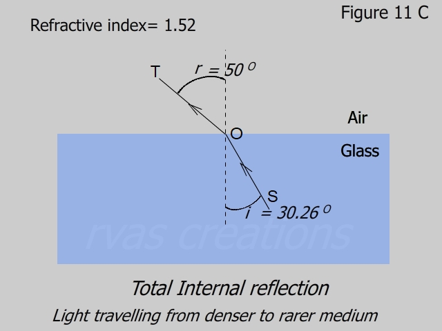
8. Total internal reflection
We saw in section 5 that, as the ray enters an optically rarer medium from a denser medium it bends away from the normal. In the following figures, the source is at S within the medium.
As the ray is going from a denser medium to a rarer medium, according to the definition of refractive index,
sin i/sin r = 1 / μ . ( Eq. 10)
Taking μ =1.52, for glass, the figures 11A to 11E are drawn for increasing values of i that yield r= 0 Deg, 20 Deg 50 Deg 70 Deg and 90 Deg.
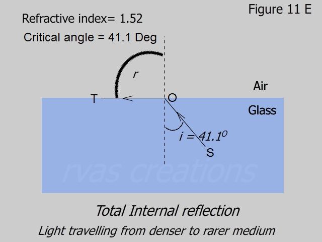
Let us see for what value of i, r becomes 90 Deg. From Eq. 10,
ic = sin-1 (sin 90 / 1.52)
= 41.1 Deg.
For a given medium ic is called the critical angle.
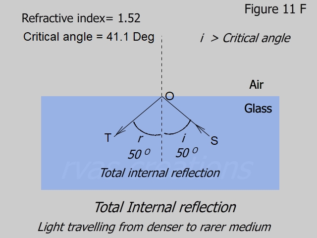
When i > ic, the refraction in the air is no longer possible and the ray undergoes total internal reflection.
As we saw in the beginning, the ray of light gets partially reflected and partially refracted. Although not shown in these figures, the ray SO always has a reflected component though small. When the ray undergoes total internal reflection, all the energy is reflected.


Total internal reflection is utilized in a right-angled prism to bend a beam by 90⁰ (Figure 12). The prism ABC has vertices angles of 90⁰, 45⁰ and 45⁰. The incident ray SO enters the prism at normal incidence on the face AB and proceeds straight through. It strikes on the diagonal face AB of the prism at point O at an incidence of 45⁰, which is greater than the critical angle ic=41⁰.1 for the glass-to-air interface.
The ray undergoes total internal reflection, meets the face CB at normal incidence, and emerges straight along OT. Thus, the original beam is bent by 90⁰. The beam can be turned at 180⁰ using a combination of these prisms. Right-angled prisms are used in binoculars, periscopes, and other instruments where light rays must be bent to compact the system.
Another example of applying the property of total internal reflection is optical fibers. As the ray propagates in the fiber, it undergoes multiple total internal reflections at the inner surface.
YouTube